Differential Pressure Decay Test

What is Differential Pressure Decay Testing?
One of the fastest methods of leak testing, differential pressure decay is well suited for many applications. Like pressure decay, this method also involves measuring the drop in pressure inside the part over time as a result of escaping material. However, in a differential pressure test, the change in pressure is measured inside the part compared to the pressure inside a control volume charged to the same pressure as the part.
The differential pressure test, like the pressure decay test, is easy to set up, but can prove much more sensitive in certain leak test applications. The sensitivity of the transducer is not related to the actual pressure in absolute or gauge pressure terms, but to the sensitivity of the differential pressure transducer at the test pressure.
How does a Differential Pressure Decay Test Work?
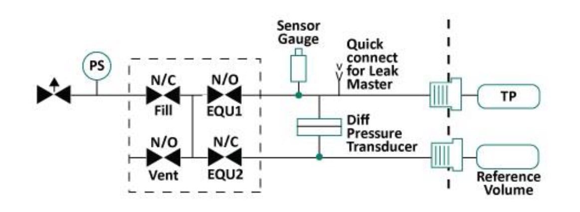
The fill step pressurizes the test part and the reference port and pressure is monitored by the gauge sensor for this step.
At the beginning of the stabilize step the fill valve closes so that no more air is allowed into the test part. The test port and reference ports of the differential sensor are still connected together. This is done so the differential sensor sees a difference of near zero pressure difference. The time is set so that the air pressure stabilizes the adiabatic effects from pressurizing the circuit. To verify that the gauge pressure is within the limits, the gauge sensor is used for this step. If too much pressure loss occurs during this step, the part either has a gross leak or the fill time is not long enough.
At the beginning of the equalize step, valves close to separate the test port and reference port of the differential sensor. This step is used to allow time for the valves to switch and for any pressure pulses that may have occurred when the valves switch to settle out. The differential sensor is the sensor that needs to be monitored at the end of this step. It is important that the differential sensor has range available when entering the measure/fine leak step. The limits for this step should be -15 to +15 mbar (or equivalent if using a different engineering unit).
The test and reference ports are still separated from each other during this step and the differential sensor is monitored for pressure changes from the beginning to the end of the step. This measurement is sometimes referred to as Delta P. Depending on the Measure Type of this step you can have the step answer in pressure change or leak rate, i.e., cc/min. The differential sensor is used for this step. If the measure type is pressure change, limits will be in mbar or other engineering units. If in leak rate, the limit units will be in cc/min or other volumetric engineering units.
The vent step is used to vent the air pressure from the part. The circuit naturally vents when not running a test so the time is used to delay the final decision until all the air escapes and it is safe to remove the part for the tester.

Testers Supporting Differential Pressure Decay Leak Test
The SaaS Sales & Marketing Acronym Bible
Industries
 English
 简体中文
简体中文
 Deutsch
 Español

