Crack Leak Test
What is a Crack Leak Test?
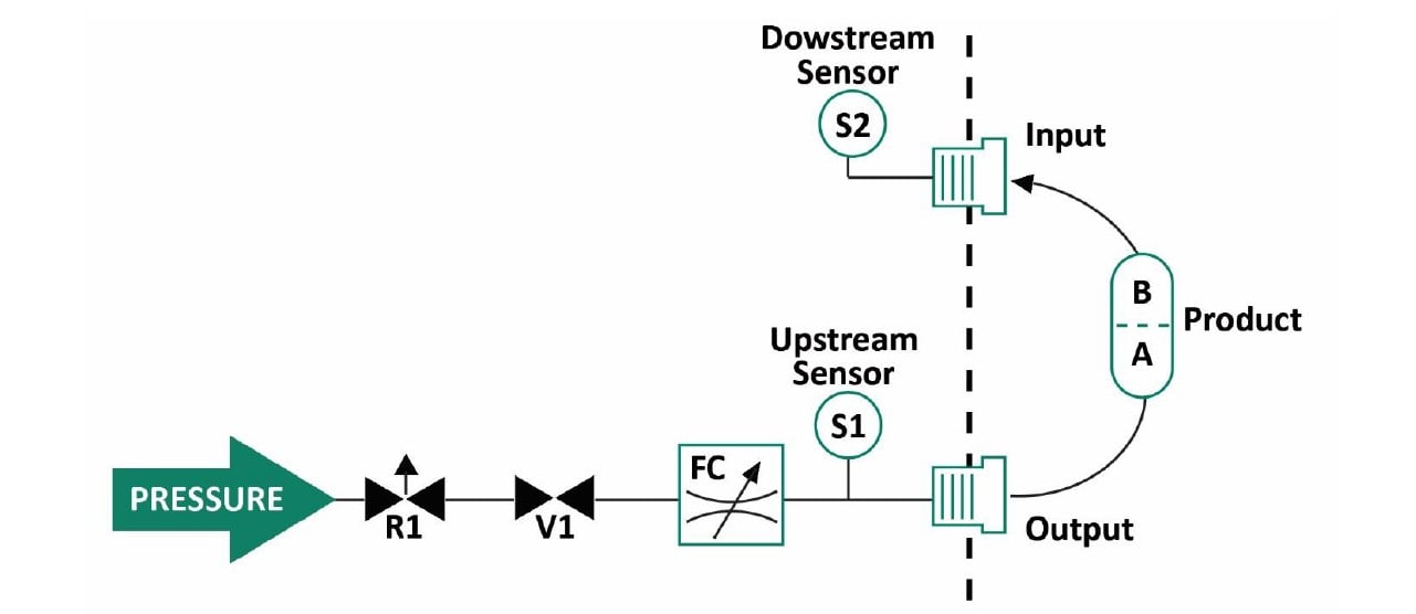
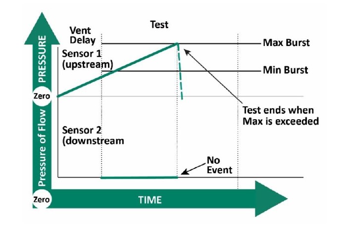
A Crack Leak test is set up to measure the pressure at which a product, such as a check valve, opens and allows air to flow through. It is used with parts that do not open quickly enough to cause a drop in the upstream pressure. An optional downstream sensor is required to measure a device that opens very slowly. Crack testing differs from burst testing because the product does not suddenly drop to zero pressure.
How is a Crack Test performed?
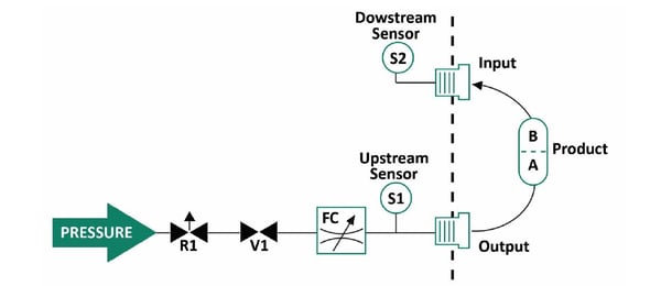
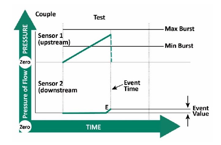
For a crack test, the leak tester uses two sensors. The standard transducer measures the pressure rise being fed to the test part, on the upstream side. The second sensor is the downstream sensor, S2. The crack event is a change in pressure or flow on the downstream side of the test part. The downstream sensor can be either a pressure or flow sensor.
The two measured values associated with the event value are:
a. Peak pressure attained. (Upstream side)
b. Amount of pressure or flow rise. (Downstream side)
Both sensors are monitored at the same time. To register as a pass, the upstream peak pressure must be within the min and max crack window AND the downstream pressure or flow must exceed the event setting. For example, if the event is set at 0.05 psig, the downstream pressure is monitored till it increases more than 0.05 psig. At that time: the peak upstream pressure must fall within the minimum and maximum crack settings for the test to pass.
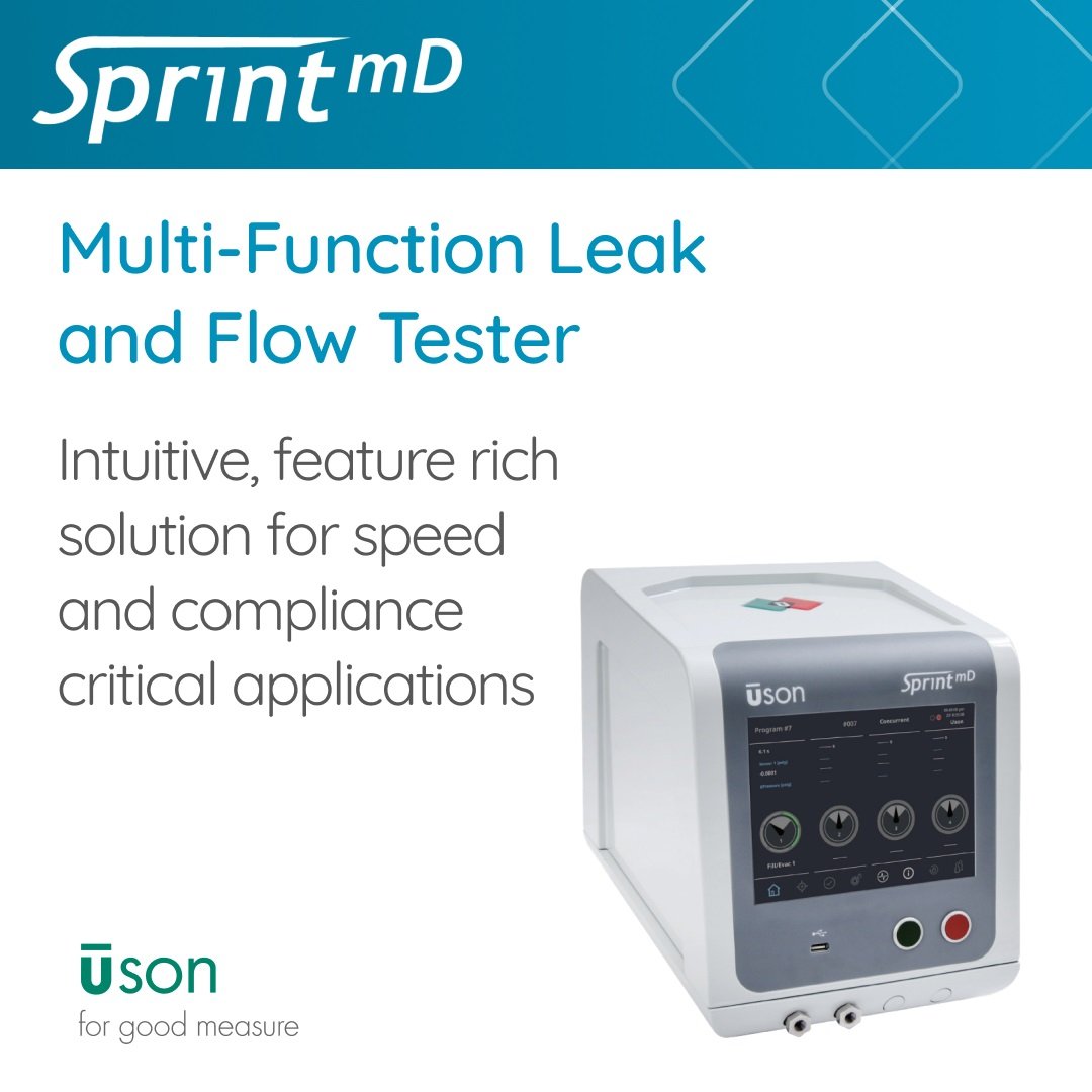
Testers Supporting Continuous Flow Tests
The SaaS Sales & Marketing Acronym Bible
Industries
 English
 简体中文
简体中文
 Deutsch
 Español

.jpg)
